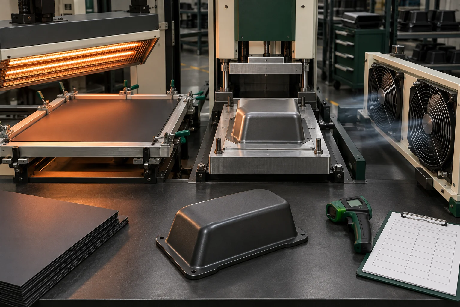
What is a thermoforming process window?
It is the documented range of inputs and observable conditions that repeatedly produces a part meeting the released geometry, appearance, formed-wall, trim, assembly and functional requirements. A process window is broader than a single oven setpoint because heater type, sheet thickness, tool mass, ambient airflow and equipment condition can change how heat reaches the sheet.
Process-window control map
| Stage | Control question | Evidence for the OEM file |
|---|---|---|
| Material preparation | Is the approved grade, gauge, surface and lot identified; is conditioning needed? | Material identity, lot and storage/conditioning record |
| Heating | Are sheet surface and core heated uniformly without overheating? | Approved heater recipe plus observation/measurement method |
| Forming | Is the sheet ready when vacuum/pressure and tool movement occur? | Cycle sequence, tool ID and critical setup checks |
| Holding/cooling | Is the part supported until it is dimensionally stable? | Cooling method and release criterion |
| Demolding | Can the part release without distortion, drag or damage? | Part/tool condition and first-off inspection |
| Verification | Does the cooled part meet released requirements? | Dimensions, wall map, appearance and functional results |
How should heating be controlled?
SEKISUI KYDEX advises against heating sheet too quickly and notes that proper core temperature matters for lower internal stress and part-to-part consistency. Its Ideal Conditions for Forming KYDEX Sheet provides thickness-dependent forming-temperature and dwell-time ranges, but also says cycle time varies with oven conditions, grade and thickness. An OEM record should therefore identify both the machine recipe and the method used to recognize forming readiness.
Published starting ranges
| Nominal sheet range | Published forming-temperature range | Buyer interpretation |
|---|---|---|
| 0.71–1.50 mm (0.028–0.060 in) | 165–177°C (330–350°F) | Starting guidance for the identified material, not a finished-part tolerance |
| 1.50–3.20 mm (0.060–0.125 in) | 182–196°C (360–385°F) | Confirm uniform heating and formed output on the actual tool |
| 3.20–12.7 mm (0.125–0.500 in) | 196–204°C (385–400°F) | Machine, gauge and application remain part of validation |
The same technical brief says sheet temperature should not exceed 204°C (400°F) and recommends keeping core temperature within 5.6°C (10°F) of the surface. CarryMold presents these as material-supplier guidance; the released production method must be validated for the quoted product and equipment.
Why is a fixed dwell time insufficient?
A timer cannot by itself prove that the sheet core is ready. The KYDEX guide describes a four-stage visual progression from initial softening and ripples to a smooth sheet with slight sag. Heater zoning, drafts around the machine and equipment age can affect that progression. A controlled work instruction can combine recipe limits with an approved visual state or suitable measurement method.
How should mold temperature and cooling be handled?
The tool removes heat from the formed sheet. A cold or uneven tool can affect local appearance and cooling rate, while premature release can allow distortion. The KYDEX guide recommends cooling the part surface below 65.5°C (150°F) before removal and, for a temperature-controlled mold, maintaining 65.5°C (150°F) during cooling without exceeding 71.1°C (160°F). These values should be recorded as cited guidance and confirmed against the specific material, tool and part.
Cooling and demolding approval
| Risk | Control | Inspection |
|---|---|---|
| Early release | Defined part-temperature or validated cycle criterion | Distortion and datum check after cooling |
| Uneven cooling | Controlled fans, mold circuits or cooling arrangement | Symmetry, twist and local appearance |
| Tool heat drift | Warm-up and steady-state definition | First-off versus stable-cycle comparison |
| Sticking/drag | Released draft, surface and removal sequence | Tool-side marks and edge condition |
What belongs in repeat-order change control?
Record material grade/gauge, supplier-approved substitutions, heater or machine recipe, forming-readiness method, tool and insert revision, vacuum/pressure sequence, cooling arrangement, release criterion and first-off checks. Revalidation should be considered when these inputs change or when a repair can affect a controlled surface.
Connect the process window to product evidence
Use this guide with the tooling design guide, forming-route comparison, formed-wall guide, defect inspection guide, quality framework and OEM workflow.
Frequently asked questions
Can the published temperature range be copied directly into a purchase order?
It can be cited as supplier guidance, but it is not enough by itself. The product still needs an identified material, machine/tool method and approved output evidence.
Is surface temperature enough to prove forming readiness?
No. The material maker emphasizes core temperature and heating uniformity because a hot surface can coexist with an insufficiently heated core.
Why compare first-off and steady-state parts?
Tool temperature and equipment conditions can stabilize after initial cycles. Comparing them helps reveal warm-up effects that a single sample may hide.
Does longer cooling always improve quality?
Not automatically. Cooling must be sufficient and reasonably even, while the validated cycle should still meet the dimensional, appearance and commercial requirements.
Turn heating and cooling into traceable OEM evidence.
Share the application, target quantity and launch requirements. We will outline the most practical sampling path.