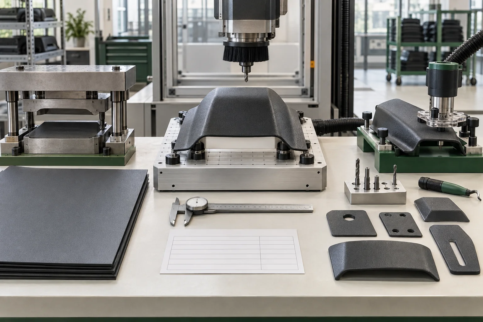
Why is trimming a separate OEM decision?
Thermoforming creates the three-dimensional shell, but the finished product still depends on its perimeter, holes, slots and mounting datums. A formed part can be cosmetically sound yet fail assembly because it was located differently in the trim fixture or because a slot shifted relative to the molded geometry. Buyers should release trimming as a controlled operation, not treat it as unspecified cleanup after forming.
Process-selection map
| Route | Best considered when | Main control |
|---|---|---|
| CNC routing | Contours, multiple features or revisions benefit from a programmable path | Part seating, fixture datum, cutter, program revision and chip/heat control |
| Punching or die cutting | Geometry is stable and repeatable features justify dedicated tooling | Punch/die identity, clearance, alignment, wear and entry/exit appearance |
| Fixture-guided routing/drilling | Samples, lower volume or simple repeatable operations fit a physical guide | Fixture wear, sequence, part restraint and operator access |
| Manual finishing | Noncritical cleanup or early development needs controlled hand work | Boundary sample, gauges, trained method and inspection frequency |
What does KYDEX technical guidance say about machining?
SEKISUI KYDEX’s Cutting and Machining KYDEX Sheet TB 153A says the material can be cut with conventional woodworking and sheet-metal shop tools. It discusses sawing and routing, notes that composition, thickness and material temperature affect material removal, and describes CNC routing with a required hold-down. Tool and process details in the current bulletin are starting guidance; CarryMold confirms the route and settings for the actual part.
Where does punching fit?
The supplier’s Punching/Perforating KYDEX Sheet TB 153B explains that the sheet may be punched or stamped and that cutting force depends on punch geometry and thickness. It also notes that stress whitening can occur at an entry hole. An OEM program should therefore approve not only the nominal hole or slot but also the tool, material condition, entry/exit face and acceptable cosmetic result.
What should a trim drawing control?
| Element | Release requirement |
|---|---|
| Datum scheme | How the formed part is located for perimeter and feature position |
| Outline | Profile, trim height, radii and transition into formed surfaces |
| Features | Hole/slot size, position, orientation and functional mating requirement |
| Edge zones | User-contact, assembly, concealed and cosmetic areas with separate criteria |
| Tooling | Fixture, cutter or punch identity and controlled revision |
| Inspection | Gauge or measurement method, sampling frequency and reaction plan |
| Change trigger | Program, fixture, cutter, punch, material, forming tool or datum revision |
Why does part seating matter in CNC trimming?
A programmed path is only repeatable relative to the coordinate system used. If the formed shell does not sit consistently against the fixture datums, the machine can follow the same path while the physical trim moves on the part. The fixture must support the actual formed geometry, restrain it without harmful distortion and prevent chips or contamination from changing its seated position.
How should volume and design changes influence the route?
Dedicated tooling can spread its cost across stable repeat production, while a programmable path can reduce the physical tooling change required for evolving geometry. Neither is automatically cheaper. Ask the supplier to separate development, trim fixture or die, programming, inspection gauge, unit operation and expected maintenance in the quotation. Connect that discussion to the MOQ and sampling-cost guide.
How is this different from edge-quality approval?
Process selection defines how the shape and features are created. The trim and edge-finish quality guide defines what the released perimeter, burrs, transitions, holes and user-contact surfaces must look and feel like. A program needs both: a controlled route and an acceptance standard independent enough to detect process drift.
What belongs in first-article evidence?
Record the material and formed-part identity, trim program or physical tool revision, fixture, cutter/punch, datum method and inspection result. Inspect feature position against the molded geometry and mating hardware, not only against an isolated flat dimension. Include the final assembled product where clips, fasteners or mounting platforms use those holes and slots. Use the first-article checklist, fastener-stack guide and quality page to connect evidence across the assembly.
What should the buyer send for quotation?
Provide 3D data or dimensioned drawings, expected annual and order quantity, feature tolerances, cosmetic zones, mating components, revision outlook and inspection expectations through the RFQ. CarryMold can then review the forming and trimming sequence as one system within the OEM manufacturing workflow.
Frequently asked questions
Is CNC trimming always more accurate?
No. Accuracy depends on the formed part, datum scheme, fixture, program, cutter condition and inspection. Automation cannot correct an unstable reference.
Can a punched hole replace a drilled or routed hole?
Only after the material, thickness, geometry, location, required edge condition and tool are validated for that feature.
Should prototypes use the production trimming method?
When trim behavior affects fit, assembly or commercial approval, production-representative evidence is preferable. If a temporary method is used, identify what must be revalidated.
When is a trim-process reapproval needed?
Review changes to the formed geometry, datum, fixture, program, punch/die, cutter, material or acceptance requirement when they can alter the released result.
Choose the trim route from the formed geometry and release evidence.
Share the application, target quantity and launch requirements. We will outline the most practical sampling path.