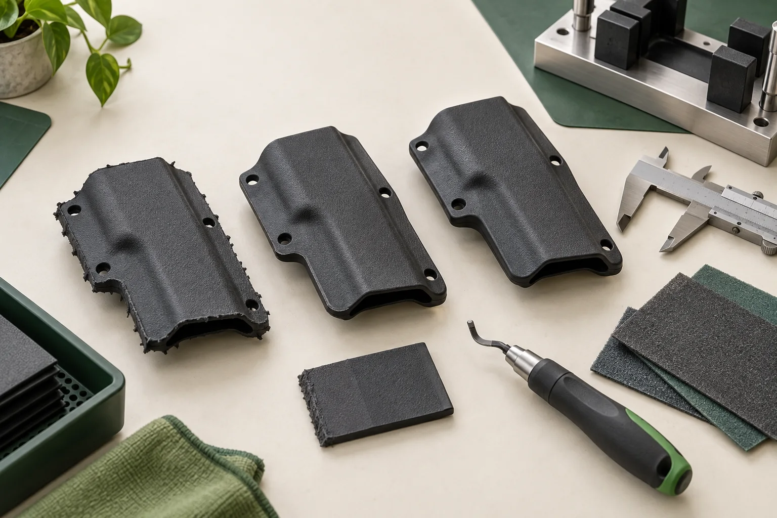
Why trimming deserves its own specification
Thermoforming creates the molded geometry, but the part is still attached to surrounding sheet until it is cut to its final outline. Trimming also establishes openings, slots and hardware holes. A formed shell can therefore look correct while an inconsistent trim line changes clearance, mounting alignment, edge appearance or the amount of material around an eyelet.
SEKISUI KYDEX’s technical brief for KYDEX sheet sheaths and holsters identifies cutting, trimming and finishing rough edges as distinct construction steps. That guidance supports the process sequence; it does not provide one universal acceptance limit for every product. Buyer and supplier must define limits for the actual geometry and intended use.
What should an OEM trim and edge specification include?
| Control area | What to define | Evidence to approve |
|---|---|---|
| Final outline | Controlled drawing, profile template or approved reference | Overlay, fixture or agreed dimensional checks |
| Critical clearances | Named zones and minimum/maximum boundaries | Configured fit and access review |
| Holes and slots | Location, size, orientation and edge distance | Gauge, measurement or installed-hardware check |
| Edge condition | Permitted burr, feathering, chips, steps and exposed layers | Visual/tactile reference under agreed lighting |
| User-contact edge | Required break, radius or polished reference | Golden-sample comparison and functional review |
| Cosmetic transition | Where texture ends and the cut edge begins | Approved photos or boundary sample |
| Cleanliness | Dust, swarf and abrasive residue limit | Final visual inspection before pack-out |
Separate rough cutting, precision trimming and edge finishing
Rough cut
Removes the formed part from excess sheet while leaving allowance for the controlled final profile.
Precision trim
Creates the released outline and functional openings using a stable fixture, template or programmed path.
Edge break
Removes burrs and sharp transitions without erasing a critical boundary or thinning an attachment area.
Finish and clean
Brings specified visible and contact edges to the approved reference, then removes debris before assembly.
How should holes and slots be approved?
Do not evaluate a hole only by diameter. Record its relationship to the trim edge, neighboring holes, molded features and the installed component. Check whether the screw head, post, washer or attachment sits as intended and whether the allowable stack clears the carried item. For elongated slots, include orientation, usable travel and end condition. Link these checks to the released fastener stack rather than accepting loose components separately.
Should buyers specify a universal edge-roughness number?
Usually not without a validated measurement method and a functional reason. Tactile feel, visible gloss and tool marks depend on material texture, edge geometry, abrasive sequence, lighting and inspection direction. A practical B2B specification can combine measurable outline and feature tolerances with a clearly identified golden sample, close-up reference photographs and defect boundaries. If a numerical surface requirement is necessary, define the instrument, direction, cutoff and sampling plan instead of stating an isolated value.
First-article trim and edge approval workflow
- Freeze the material grade, nominal gauge and formed configuration.
- Identify datum logic and the final outline revision.
- Mark functional clearances, user-contact edges and cosmetic zones.
- Measure critical holes, slots, edge distances and trim boundaries.
- Install the released hardware stack and mounting interface.
- Review configured fit, access, retention and component clearance.
- Approve close-up edge references under agreed lighting.
- Record permitted minor conditions and reject conditions.
- Retain the approved part, photographs and inspection results.
- Require reapproval after changes to tooling, fixture, cutting method, material or critical geometry.
Common trim conditions and the evidence to request
| Observed condition | Possible process area | Useful evidence |
|---|---|---|
| Variable outline | Part location, fixture stability or trim path | Overlay results and fixture review |
| Burrs or feathered edge | Tool condition, direction, support or finishing | Close-up photos and tool/change record |
| Chipped corner | Geometry, support, cutting load or handling | Location map and repeat-sample review |
| Misaligned hole pattern | Datum, drill fixture or formed-part shift | Feature measurements and installed assembly |
| Over-polished boundary | Manual finishing variation | Golden-sample comparison and work instruction |
| Debris at assembly | Cleaning and pack-out control | Final inspection and containment record |
How this guide fits the wider quality plan
Use the trim specification with CarryMold’s thermoforming-defect guide, first-article inspection checklist, golden-sample approval guide, quality framework and OEM development workflow. Together they separate formed-surface conditions, final geometry, assembled function and repeat-production evidence.
Frequently asked questions
Is a polished edge always the correct finish?
No. The required finish depends on the released product, material texture, cosmetic target and contact zone. Approve a specific reference instead of assuming maximum gloss is always desirable.
Can the unassembled shell pass trim inspection?
It can pass intermediate profile checks, but final approval should also verify the installed hardware, mounting interface, fit reference and required clearances.
When should trim quality be reapproved?
Reapprove after a change to outline data, trim tool, fixture, cutting method, abrasive sequence, material, forming tool or any feature that changes how the part is located and cut.
Does this guide set a universal burr or radius limit?
No. It provides a control framework. The buyer and supplier must agree product-specific limits and evidence based on geometry, contact, appearance and intended use.
Release the final edge as part of the product specification.
Share the application, target quantity and launch requirements. We will outline the most practical sampling path.