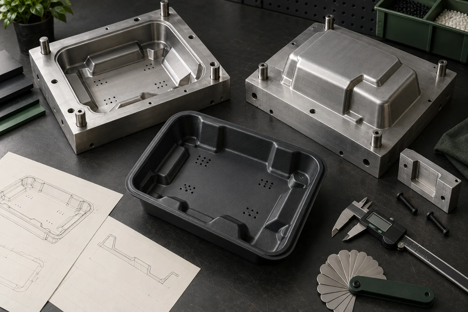
Why does tooling design matter to an OEM buyer?
The forming tool converts a flat sheet into the controlled geometry that later receives trimming, holes, hardware and functional inspection. Tool shape affects detail, wall distribution, release, cosmetic surfaces and repeatability. A purchase specification should therefore connect the tool revision to the approved sample and define which changes trigger another first article.
Male versus female thermoforming tools
| Decision | Male tool | Female tool | Buyer evidence |
|---|---|---|---|
| Forming direction | Sheet forms over an external shape | Sheet forms into a cavity | Section view and draw direction |
| Tool-side detail | Directly defined on the internal formed face | Directly defined on the external formed face | Named cosmetic and functional surfaces |
| Wall distribution | Material first contacts the tool near its high regions | Material stretches toward the cavity depth | Critical formed-wall measurement map |
| Release | External walls need suitable draft and clearance | Cavity walls and trapped geometry need suitable release | Approved draft, split or removable-feature plan |
| Selection basis | Choose from tolerances, detail side, geometry, process and assembly requirements | Controlled CAD/drawing and sample | |
What draft and corner radius should be specified?
SEKISUI KYDEX lists useful starting values in its Ideal Conditions for Forming KYDEX Sheet: male tools use a 2–4° minimum draft and 2.30 mm (0.094 in) minimum radius; female and pressure-forming female tools use a 1–2° minimum draft and 1.60 mm (0.063 in) minimum radius. These are process guidance, not automatic finished-part acceptance limits. Sheet gauge, draw depth, texture, release direction and functional geometry can require a different design.
Tool-geometry approval table
| Feature | Why it matters | What the buyer should release |
|---|---|---|
| Draft | Supports part removal and reduces tool locking | Angle by face and draw direction |
| Inside/outside radii | Affect material flow, corner thinning and tear risk | Critical radius locations and minimums |
| Vacuum holes or slots | Remove trapped air and influence local detail | Vent location strategy plus acceptable witness marks |
| Undercuts | May prevent release from a rigid one-piece tool | Allowed feature, split line, insert or articulated mechanism |
| Cavity spacing | Affects material distribution and webbing in multi-up tools | Tool layout and part orientation |
| Shrinkage allowance | Connects hot-tool geometry to cooled-part dimensions | Material/process basis and finished-part datums |
| Surface finish | Can transfer tool-side appearance and affect release | Functional/cosmetic zones and physical reference |
How should vacuum vents be controlled?
Vents need to evacuate air from low points and detail regions without creating unacceptable marks. More or larger holes are not automatically better: the KYDEX thermoforming troubleshooting guide connects blocked or insufficient vents with poor detail, yet also connects oversized vents with raised “nipple” marks. Define acceptable tool-side witness marks and verify the released vent arrangement on the first article rather than treating vent diameter as a universal product specification.
What happens when the part includes an undercut?
An undercut can trap a cooled formed part on a rigid tool. Practical options include changing the geometry, using an approved split or breakaway tool, adding removable inserts, or using articulated tooling where the program justifies it. Record the assembly and removal sequence, wear points and insert identity so tool maintenance does not silently change the product.
How should shrinkage and dimensions be handled?
The same KYDEX forming guide gives approximate mold-shrinkage starting ranges: 0.40–0.60% for male tools, 0.50–0.70% for female tools and 0.40–0.50% for pressure-forming female tools. Do not convert these ranges into a guarantee for an unspecified part. Release finished-part datums and tolerances, identify the material and process, then use measured first articles to confirm or correct the tooling allowance.
Tooling approval package
Input definition
Released CAD or drawing, material identity, starting gauge, forming route, draw direction and approved configurations.
Critical geometry
Datums, fit surfaces, trim allowance, radii, draft, clearances, mounting features and prohibited contact zones.
Tool construction
Male/female type, cavity layout, vents, inserts, split lines, surface finish and tool identification.
Validation
First-article dimensions, formed-wall map, appearance, functional checks, golden sample and change triggers.
Connect tooling to product approval
Use this guide with the forming-process comparison, formed-wall thickness guide, defect inspection guide, first-article checklist and OEM development workflow.
Frequently asked questions
Is one draft angle suitable for every KYDEX tool?
No. Published values are starting guidance. Tool type, draw depth, texture, undercuts, material gauge and removal direction can require more draft or a different release method.
Should an OEM buyer specify vacuum-hole diameter?
Usually the buyer should specify required detail and acceptable witness marks while the manufacturer controls a validated vent design. A critical vent feature can be recorded when it affects the approved result.
Can the tool CAD alone serve as the product specification?
No. Tool CAD describes tooling geometry, not every finished-part requirement. The product still needs datums, dimensions, trim, formed-wall, appearance, assembly and functional acceptance criteria.
Does a tooling repair require a new first article?
It depends on scope. Repairs or insert changes that can affect controlled geometry, surface, vents, release, wall distribution or assembly relationships should trigger documented review and appropriate revalidation.
Release the tool and the finished-part evidence as one controlled OEM program.
Share the application, target quantity and launch requirements. We will outline the most practical sampling path.