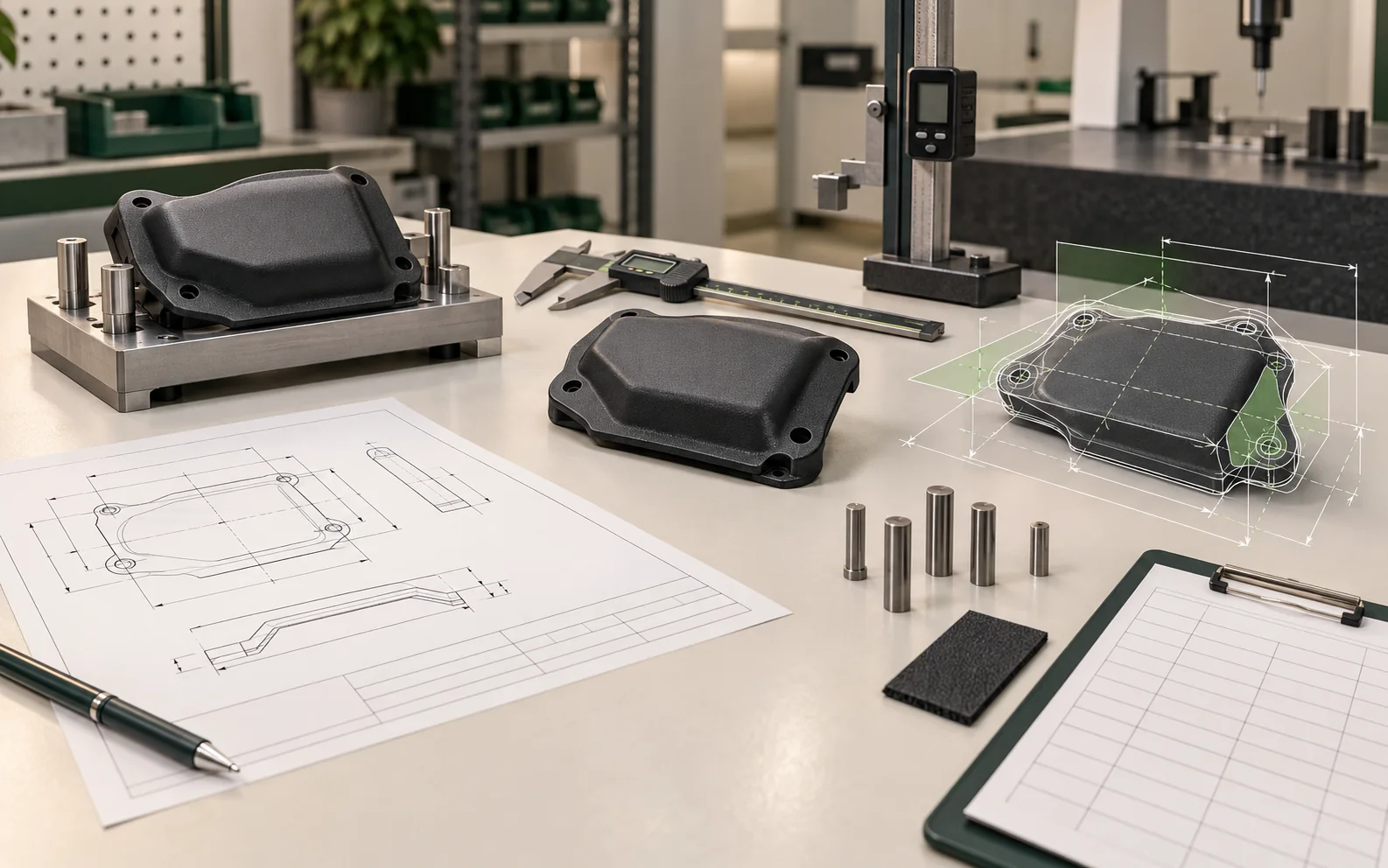
Why do thermoformed plastic drawings need a different approach?
A flat sheet becomes a three-dimensional part through heating, stretching, tool contact, cooling and trimming. Material behavior, local draw, tool temperature, cooling and release can influence thickness, profile and free-state shape. The Society of Plastics Engineers Thermoforming Division notes in its Thermoforming 101 design article that design accuracy, draft, wall distribution and trim capability must match the actual forming process. A drawing should therefore control function without pretending that every surface behaves like machined metal.
What information belongs on the drawing?
| Drawing element | Buyer decision | Release evidence |
|---|---|---|
| Material callout | Grade, nominal gauge, color, texture and approved alternative policy | Purchase specification and incoming identity |
| Tool side | Which surface is governed by tool geometry and which is non-tool/free | CAD orientation and approved sample |
| Datum scheme | How the flexible part is located without artificial distortion | Inspection fixture and datum sequence |
| Trim and features | Perimeter, holes, slots, edge zones and feature-to-datum locations | Trim program/tool revision and measured first article |
| Functional profile | Where fit, clearance, retention or mounting geometry matters | Profile check, mating gauge or representative assembly |
| Inspection state | Free state, restrained fixture state, temperature and conditioning | Inspection instruction and report |
How should datums be selected?
Choose datums from stable features that represent how the part locates in use or assembly. A primary support area can establish orientation; holes, slots or controlled edges can clock and locate the part. Avoid using a flexible non-tool surface as if it were a rigid precision plane. The fixture should support without forcing the part into compliance, and the drawing should state whether a measurement is made free or restrained. The datum order, contact points and fixture revision belong with the first-article record.
Which dimensions should be critical?
Critical dimensions should trace to a function: mating-part clearance, mounting-hole position, protected geometry, retention interface, user-contact edge or assembly envelope. Overall dimensions can be useful, but they do not replace feature-to-datum locations. Reference dimensions may communicate intent without creating redundant acceptance conflicts. If every dimension is marked critical, the drawing no longer helps production or inspection prioritize risk.
Are tool-side and non-tool-side dimensions equivalent?
No. A tool-contact surface follows the controlled mold more directly, while the opposite surface reflects local formed-wall thickness and material distribution. SEKISUI KYDEX explains in Fundamentals of Thermoforming TB 140A that process route affects detail and dimensional capability. A dimension to a free surface may need a wider limit, profile zone, mating gauge or reference-only treatment instead of a tight point measurement.
How should holes, slots and trim edges be controlled?
Locate post-trim features from the functional datum scheme, not only from a changing free edge. State hole or slot size, position, edge distance where functional, and whether countersink, relief or hardware seating is required. Separate the feature location from cosmetic edge acceptance. The post-forming trimming process guide explains how CNC, punching and fixture-guided routes change tooling, revision cost and inspection evidence; the trim and edge-finish guide covers burr, contact-zone and edge acceptance.
Why should a buyer avoid copying generic tolerance tables?
Published tolerance guides describe a supplier’s process assumptions, tool classes, materials and part sizes. For example, Profile Plastics’ thermoforming tolerance guide separates formed dimensions from trimmed dimensions and notes that material and geometry can require additional allowance. Those values are useful evidence that capability depends on the feature and process, but they are not CarryMold guarantees. Quote-specific limits must be reviewed against geometry, gauge, tooling, trim method, measurement and quantity.
What does ISO 20457 add to the discussion?
ISO 20457:2026 explains the broader principle that molded plastics can vary because of material behavior, shrinkage, processing, geometry, warpage and non-uniform cooling, so metal tolerance approaches do not transfer automatically. Its listed primary processes are not a substitute for a thermoforming-specific capability agreement; use the principle to structure buyer-manufacturer discussion, not to claim automatic conformity.
How should measurement conditions be released?
Define the instrument or gauge, datum fixture, restraint, measurement points, temperature/conditioning if relevant and reporting precision. SEKISUI KYDEX’s forming guidance TB 140C connects cooling before demolding to distortion risk. A report made immediately after forming may not represent the same state as a conditioned assembly check. Time, restraint and method should be consistent enough that supplier and buyer can reproduce the result.
What should the first-article package contain?
Release the drawing revision, material identity, approved CAD, tool and trim revision, inspection fixture revision, measurement report, deviation list and photographs or physical sample identification. Use the first-article checklist to connect dimensions with appearance, hardware and functional checks, then retain the golden sample as a physical interpretation aid. A sample never replaces explicit dimensions, but it can resolve texture, edge and tactile attributes that are difficult to describe numerically.
What should change control cover?
Reapproval triggers can include material grade or gauge, forming tool repair, fixture replacement, trim program or die revision, hole-pattern change, cooling method, mounting hardware or measurement-method change. The OEM manufacturing workflow should link these changes to the affected drawing characteristics rather than treating every revision as equivalent.
What should an OEM buyer send for quotation?
Send the 3D model, dimensioned drawing, mating references, application, material target, expected quantity, critical interfaces, inspection state and known regulatory constraints through the RFQ. Mark assumptions and open questions rather than filling gaps with arbitrary tolerances. CarryMold can then review which characteristics need a fixture, sample study or negotiated capability before production release.
Frequently asked questions
Can a golden sample replace a dimensioned drawing?
No. It helps interpret appearance and function, but controlled dimensions, material and revision information are still needed for repeat production.
Should every surface receive a profile tolerance?
No. Apply profile or dimensional controls where they protect fit or function, and identify noncritical surfaces appropriately to avoid unnecessary inspection and cost.
Can finished-part tolerances be inferred from flat-sheet tolerances?
No. Sheet gauge and size are inputs; forming, draw, cooling, trimming, geometry and measurement state affect the finished part.
Does this guide publish CarryMold’s standard tolerances?
No. It is a drawing-review framework. Achievable limits require a quote-specific review of the identified part, material, tooling, process and inspection method.
Keep wall thickness separate from drawing dimensions
Finished-part tolerances define inspectable geometry. Use the KYDEX sheet and formed-wall thickness guide to define nominal gauge, draw-related thinning and critical wall-measurement locations.
Turn the CAD file into an inspectable OEM release package.
Share the application, target quantity and launch requirements. We will outline the most practical sampling path.